Overview
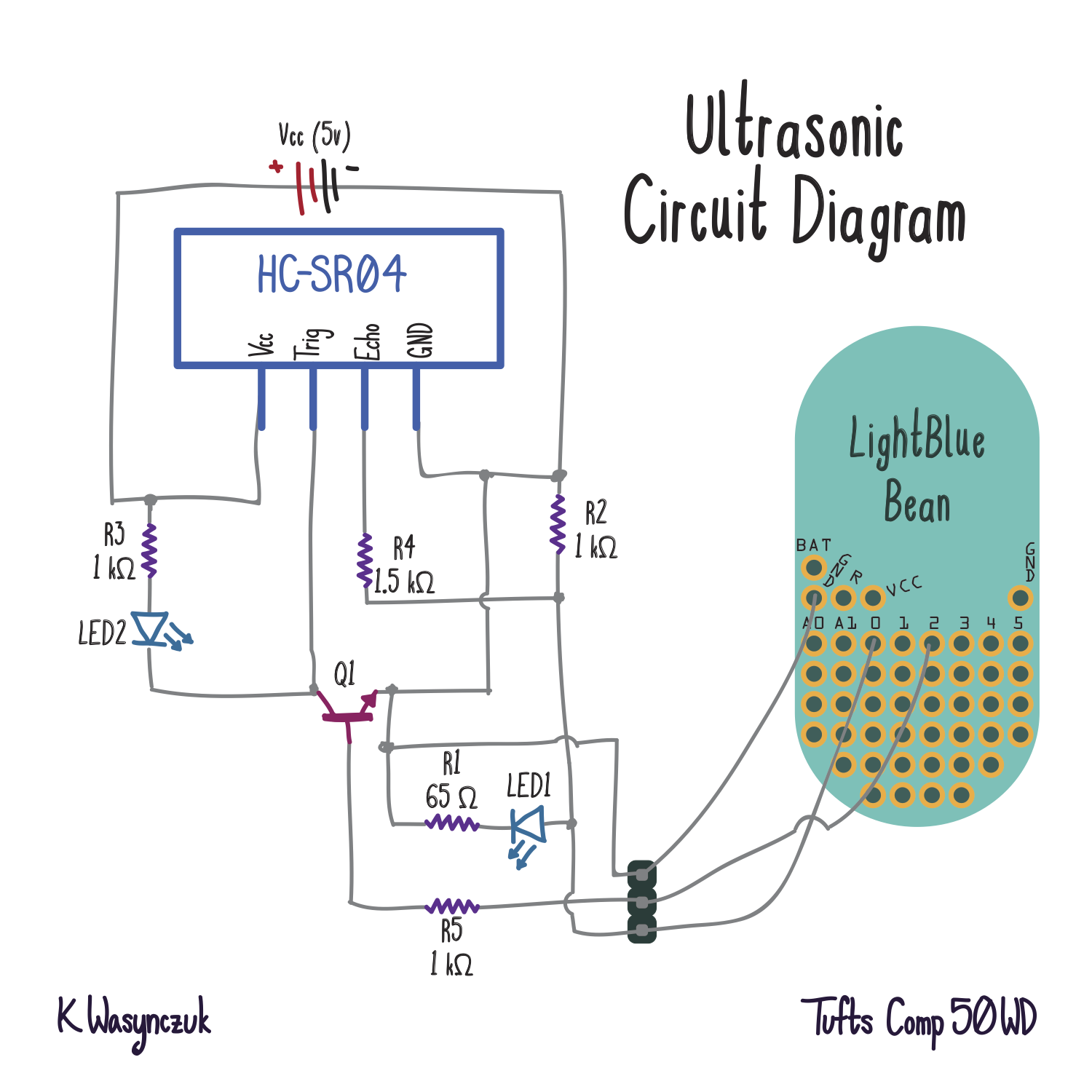
In this project, you will be working with a “sonic motion sensor” (HC-SR04) that determines the distance from the sensor to an object that the sensor is pointed at. The range for the HC-SR04 is between 2 centimeters and 4 meters, giving a user a short-range distance measurement capability. Your projects will first be put together on a breadboard based on a circuit diagram that we provide to you below, and will provide distance information through the LightBlue Bean (see template below), which will then forward the data to either an iPhone application or a Mac OS X application (provided for you). Additional parts of the project will include mocking up your device in Fritzing in the breadboard and schematic view, and also soldering parts to a printed circuit board (PCB) that we have designed and had fabricated based on the schematic we have below. Finally, you will be tasked with designing a reasonable real-life use case for your device that can be used in the real world as a wearable.
Teams:
- Students must work in teams of two for this assignment
» Project 2.1: due 2/24
- Real Breadboard Prototype and Fritzing breadboard mock up. Your breadboard will be based on the circuit below. (Due: Wednesday, Feburary 24th, in class. Please build your circuit on a small breadboard).
» Project 2.2: due 2/29
- Surface mount soldering. We will provide you a PCB and components, and you need to solder the components and make the sonic motion circuit work (Due: Monday, February 29, in class).
» Project 1.3: due 3/2
- Real world wearable using the sonic motion PCB circuit (Due: Wednesday, March 2, in class. You will demonstrate your wearable to the class).
Grading:
- Each part of the project will be graded individually, for a total of three grades for the project. Each sub-project grade will be weighted the same.
Parts
For the Breadboard :
For Surface Mount:
- Ultrasonic range sensor (part #: HC-SR04)
- LEDs (2; different colors)
- resistors:
- 1k ohm (x3)
- 1m ohm (x1)
- 82 ohm (x1)
- NPN transistor (we will discuss transistors this week!)
For Surface Mount:
- same as above (but surface mount..)
- 9v Barrel Jack for power
- 5v Voltage Regulator
- Capacitors (x2)
Hints
- The datasheet for the SR-HC04 is located here: HC-SR04 - Micropik
- The SR-HC04 requires 5V to power the device, and the Light Blue Bean can only use 3.3V. Your power supply can support both 5V and 3.3V simultaneously, although we suggest you power your Bean from the coin-cell and use the power supply for 5V.
- Remember to connect your Bean’s ground to the ground of the power supply. All devices must have a “common ground” and this is the way to accomplish that.
- Suggestion: follow the schematic diagram exactly for your breadboard initially. If you want to make additions to your circuit, make sure you can get the original idea working perfectly before making modifications.
- Be very careful with the input to your Bean pins. Remember, they only take up to 3.3V. We have put a “voltage divider” circuit that connects to the Bean input pin to limit the voltage to 3V.
- On the schematic, wires that overlap only connect if there is a dot.